 emerysteele.comBohdan's corner of the Internet.
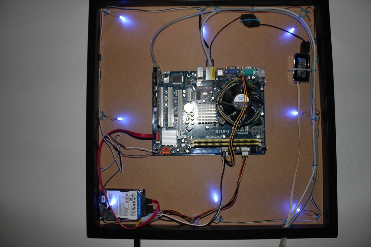
In this project, I made a device that shows internet status using LEDs. I used red and blue LEDs because it went well with my overall design, but you may use any colours you like. Keep in mind that different LEDs have different forward voltage and current and may require different resistors. To calculate the resistance needed, check out http://www.hebeiltd.com.cn/?p=zz.led.resistor.calculator.
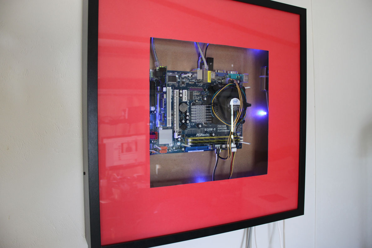
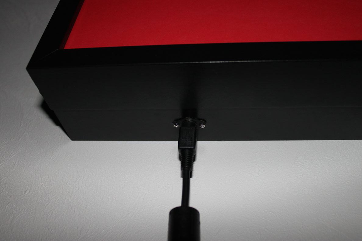
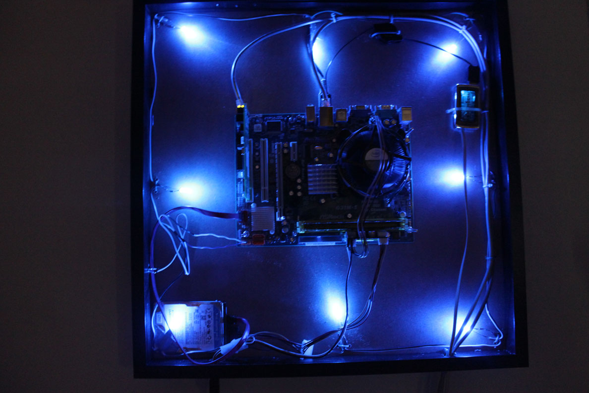
This device works by the arduino sending a ping command to a program called GoBetwino every 90 seconds. GoBetwino then pings the specified server and returns either a 0 or -1 to the arduino. 0 meaning the server was pinged succesfully and -1 meaning it failed. The arduino will then turn on the right colour of LEDs indicating the status of the internet. I have also programmed the arduino to send an email command to GoBetwino if the internet has been out longer than 1 minute. I have wired all of this into my custom computer case that I made from two Ikea picture frames.
Here is a schematic for this project using multiple LEDs:

Here is a simpler schematic using only 2 LEDs:

Here is the arduino sketch:
// This script is to be used in conjuction with GoBetwino to check
// if the internet is working on the machine the arduino is attached
// to. Get GoBetweeno at http://mikmo.dk/gobetwino.html
// Variables:
const int ledRed =  6;  // pin for Red LED
const int ledBlue =  10;  // pin for Blue LED
const char PingCMD[] = "PING";  // command configured in gobetwino for pinging
const char EmailCMD[] = "EMAIL";  // command configured in gobetwino for emailing
const int DefaultPingInterval = 90000; // how often should the ping command be excecuted
const int netOutTime = 60000;  // minimum internet outage time for email to be sent
const char emailAddy[] = "example@example.com";  // the email address to send emails to
// Nothing below this line should be changed unless you know what
// you are doing.
int incomingByte = 0; // for incoming byte from serial
int FirstLoop = 1;  // for indicating first loop
int waitingforSerial = 0;  // for indicating if script is waiting for response from serial
int PingInterval = 0;  // for storing ping interval
int LastWasBlue = 1;  // for determining if last color was blue
unsigned long currentTime = 0;  // for storing current time
unsigned long timerStart = 0;  //  for storing the time at which the timer started
void setup() {
  Serial.begin(9600);  // begin serial at 9600 baud
  pinMode(ledRed, OUTPUT);  // set ledRed pin as output
  pinMode(ledBlue, OUTPUT);  // set ledBlue pin as output
}
void loop(){
  currentTime = millis();  // set current time to millis
  unsigned long timePassed = currentTime - timerStart;  // get time difference between currentTime and timerStart
  if (FirstLoop == 1)  // if script is on first loop
  {
      digitalWrite(ledRed, HIGH);  // turn red led on
      digitalWrite(ledBlue, LOW);  // turn blue led off
      FirstLoop = 0;  // set FirstLoop to 0
      PingInterval = DefaultPingInterval;  // set ping interval to default
  }
  else
  {
    if (waitingforSerial == 0)  // if waitingforSerial is 0
    {
      delay(PingInterval);  // delay script by PingInterval
      Serial.print("#S|");  // send ping command to serial
      Serial.print(PingCMD);  // "    "     "     "    "
      Serial.println("|[]#");  //"    "     "     "    "
      waitingforSerial = 1;  // set waitingforSerial to 1
    }
    else
    {
      if (Serial.available() > 0)
      {
        delay(100);
        incomingByte = Serial.read();  // read the incoming byte
        if (incomingByte == 48)  // if server was pingable
        {
          if (timePassed >= netOutTime)  // if timePassed is greater than or equal to wait time
          {
            if (LastWasBlue == 0)  // if last color was not blue
            {
              Serial.print("#S|");  // send email command over serial
              Serial.print(EmailCMD);  //"    "     "      "     "
              Serial.print("|[]#");  //"    "     "      "     "
            }
          }
          digitalWrite(ledBlue, HIGH);  // turn blue led on
          digitalWrite(ledRed, LOW);  // turn red led off
          PingInterval = DefaultPingInterval;  // reset PingInterval to default value
          LastWasBlue = 1;  // set LastWasBlue to 1
          waitingforSerial = 0;  // set waitingforSerial to 0
          timerStart = 0;  // reset timerStart
        }
        if (incomingByte == 49)  // if server was not pingable
        {
          digitalWrite(ledRed, HIGH);  // turn red led on
          digitalWrite(ledBlue, LOW);  // turn blue led off
          PingInterval = 5000;  // lower ping interval to 5s
          waitingforSerial = 0;  // set waitingforSerial to 0
          if (timerStart == 0)  // if timer has not already started
          {
            timerStart = millis();  // set timerStart to current time
          }
          LastWasBlue = 0;  // set LastWasBlue to 0
        }
      }
    }
  }
}
Files:
sketch_jun28a.pde (3.77 kb)
Schematic_bb.svg (416.32 kb)
Schematic_schem.svg (94.70 kb)
Schematic-Simple_bb.svg (253.87 kb)
Schematic-Simple_schem.svg (65.96 kb)

